Introduction
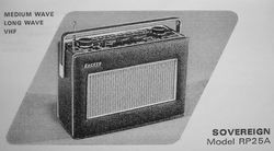
At some point last year I got one of these guys as a project-gift: a Hacker Sovereign II from 1969. It wasn't working and the store chappy said (according to the person who gave me the gift) "I'm not sure what's wrong with it". Then the first part of the project was to make the radio work. However, once I got it running, I figure it out that the batteries it uses are scarce and expensive. It uses two PP9 batteries and they sell for about 5 pounds each. I'd have got a rechargeable battery back or something like that, but I decided that it would make a good project to convert the radio to be able to plug it into the mains. The main objective was to allow the radio to function from batteries or mains, in case it's needed for a last minute barbecue.
Fixing the radio
From a first inspection, nothing really obvious was telling what was wrong with the radio. There wasn't a big melted chunk in the middle nor an intergalactic parasite living inside it. So discarding these obvious alternatives, I invested in the manual and bought it from this webpage http://www.service-data.com/section.php/3493/1. The manual comes with the radio circuits so I figured out which piece was missing. Somehow, the radio overheated and one of the resistors got disconnected. After fixing that, the radio was working perfectly. But why stop there? I mean, I didn't even have the chance to break something or get a couple of electric shocks. Let's transform it to mains! Ah! Btw, at this point I bough a cheap UNI-T (best name ever) Digital Multimeter from Maplin (N15BY). While it's pretty simple and it won't save me from a zombie apocalypse, it suits all these wee projects perfectly.
Conversion to mains: first attempt
By this point I had some basic notions of circuits, enough to build up some knowledge, but I didn't know what exactly had to be done to properly convert the radio. I discovered that a more advance version of my radio (the rp25b) included a connection to mains. You can see the circuit below:
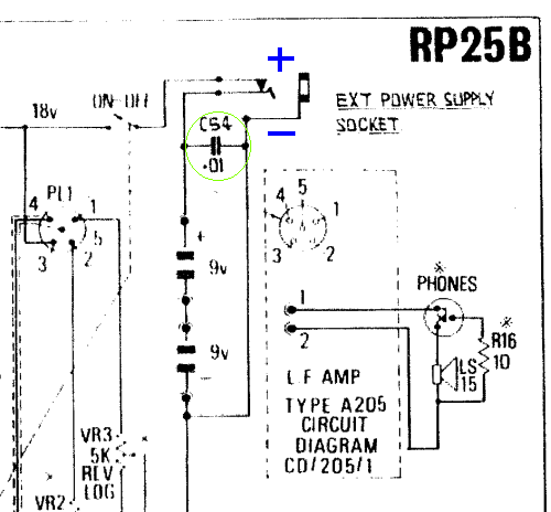
Before continuing, a quick word about the two 9 v batteries you can see in the figure. About these guys: old-school pp9 batteries are massive and have a brutal capacity of around 4500 mAh. The radio consumes around 21 mAh, so a couple of pp9s will keep you going for a while. Going back to the rp5b, you connect the socket in the + and - points showed in the picture, but using my super-incredible Sherlock Holmes level observation skills, I saw that guy in the green circle. I knew what a capacitor did, but why, how, panic!!
I quickly figured out that this capacitor is a "decoupling capacitor" which opened the pandora box.
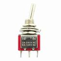
My first attempt was to connect the radio using a switching 18 V dc source for Mapling and a 0.01 uF capacitor for decoupling. Because I wanted to keep the radio's circuit intact, I also added a 3 ways toggle switch so I'd choose between Batteries or Mains.
Before energising the radio, I always measure the voltage with the Multimeter to avoid some component exploding in my face! All cool, 18 V... but the result wasn't what I could have expected. While it didn't exploded, it produced a lovely sound that you can here in this link: http://jorgepena.net46.net/AudioRecording.mov. As you can hear, it is not exactly the kind of pure and smooth sound you want your radio to make. I thought a furious blue bottle in heat fly was trapped in the radio and it was being stimulated by the Maplin power source. Surprisingly, there wasn't a blue bottle trapped inside and what I was hearing was the 60 Hz switching source: my circuit didn't have enough smoothing and decoupling.
Circuit smoothing and decoupling
After some research, I figure it out the need for decoupling and smoothing the DC source even further than adding a single capacitor. What it worked at the end was a combined solution. The circuit is decoupled in several stages and also I'm regulating (lowering) the voltage, taking it to around 16V so I can get rid of the peaks. Below you can see the final circuit.
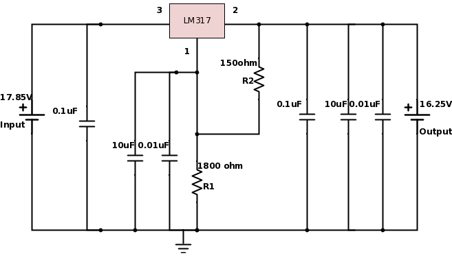
As you can see, I'm decoupling the input, the output and the voltage regulator leg of the LM317. Depending on the capacitance I'm using ceramic (for the smaller ones) and electrolytic (for the bigger ones) capacitors. Remember to be careful of connecting the electrolytic capacitors in the right direction!
After all this, I wasn't getting quite the result I wanted still. So I decided to change the source for a better one and I found just the right one for the job.
After all this, I wasn't getting quite the result I wanted still. So I decided to change the source for a better one and I found just the right one for the job.
New DC source
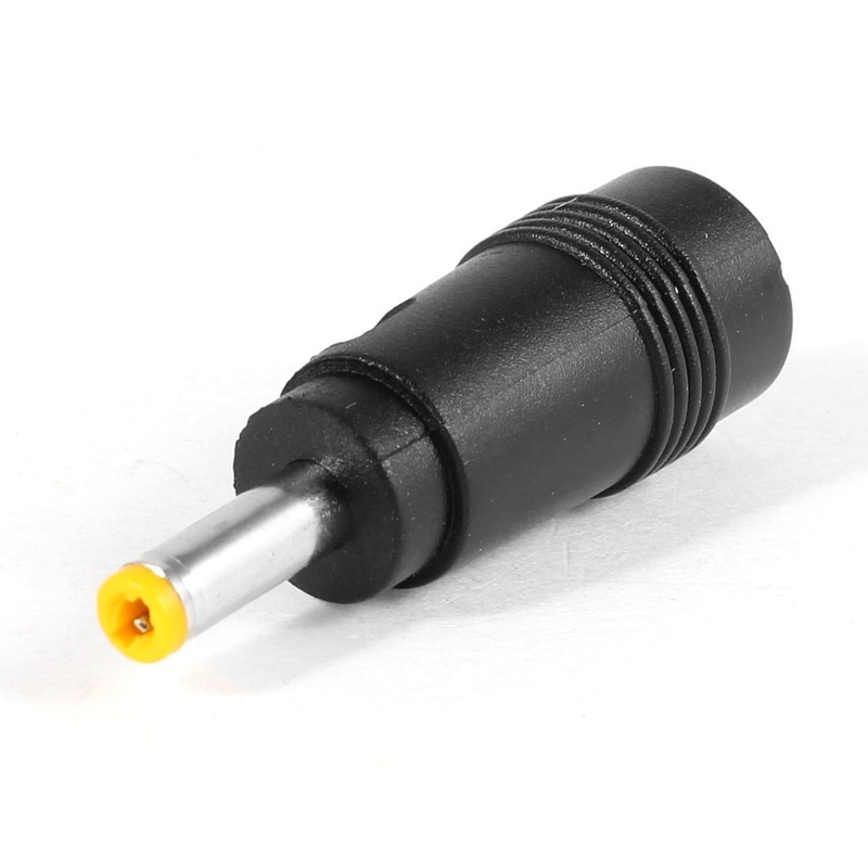
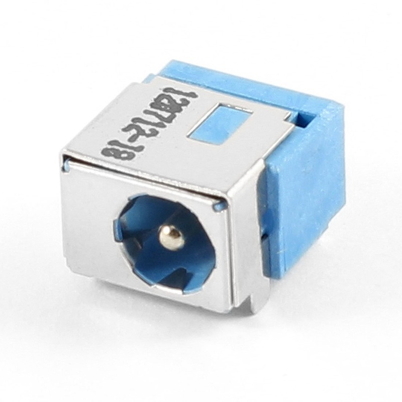
I found an old computer charger which provided 19 V at 2 A. I tested it with a non-definitive cable connection and I added a 50 mA fuse, just in case. The result was amazing: no buzz at all and pure beautiful sound coming out of the Hacker. However, the project wasn't done. The power source had a yellow pin-type connector. The only female plug I could find with these type of connector was a laptop replacement (for Acer computers).
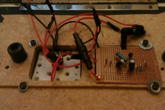
The result!
Finally, you can see the final circuit (just before the final soldering). I replaced the original panel in the back of the radio just in case I want to roll the modification back to original. I still need to paint the new panel or cover it with faux leather or something like that...